The stonemasons of the Inca Empire knew nothing of cement. On the other hand, they mastered their technique to such an extent that they were able to assemble cut stone with a perfect joint, the technicality of which still impresses us today.
The largest block below, famous for its 12 angles, is around 1 m high. Laid down 7 centuries ago, it is part of a wall in the city of Cuzco, Peru.

Figure 1: The 12-cornered stone from Cuzco
Optimal use of space is also the aim of modern-day technicians. In contemporary buildings, putting the right piece of the jigsaw in the right place remains the priority. Because the right placement of materials and systems determines the comfort and quality of life of occupants.
An analogy: with the right arrangement of ceiling fans, volumes of moving air will fit together as perfectly as volumes of frozen stone.
Ceiling fan layout: saving means and resources
Why is precise adjustment of the different air mixers so important?
Two imperatives must be reconciled: the budgetary imperative and the thermal comfort imperative.
Trop peu brasseurs d’air dans un espace donné, et le confort devient insuffisant.
Too few fans in a given space, and comfort becomes insufficient.
Too many ceiling fans in the same space, and the budget gets out of hand.
The layout is not limited to these imperatives:
- aesthetics,
- minimum spacing between fans and vertical walls,
- potential conflict with lighting
- the passage of networks.
Layout of bladed ceiling fans: a limited cone of influence
These ceiling fans are often powerful, but their area of influence is often limited, as shown in the visual below.
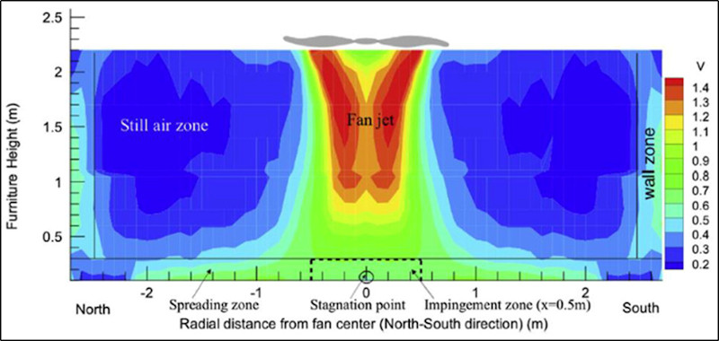
Figure 2 – Air velocity distribution with a bladed fan (Source: Gao et al., University of California at Berkeley)
In these conditions, it’s worth taking into account feedback from the tropical zones of overseas France. In these latitudes, recommendations are already in place for standard air fans (1.32m diameter).
Homes
RTAA DOM (voir p.12) et RT Guadeloupe (see p.37): a fan must be installed in each bedroom. In the living room, one fan is required for a surface area of up to 20 m², and two above that.
Offices
The RT Guadeloupe stipulates a minimum density of 1 point for every 20 m² of floor space occupied by workstations or public reception areas.
Classrooms
There are no regulations to speak of, but feedback recommends densities of 1 ceiling fan (with a minimum diameter of 1.32 m) for a surface area of 10 to 12 m².
A specific ceiling fan should be installed at the teacher’s workstation, both for performance reasons and to take into account the particular spatial positioning of teachers.
What distance should be allowed between ceiling fans and walls, and between the fans themselves?
Aerodynamics is a complex discipline.
On ambitious projects, CFD (Computational Fluid Dynamics) simulations can be carried out. Naturally, such studies are costly, and cannot be systematized for all projects.
Today, experience feedback leads us to consider the following layouts:
- Minimum fan-wall spacing: 1 blade diameter (e.g. 1.32m)
- Minimum fan spacing: 2 blade diameters
- Even fan distribution in the room
This rules out the installation of fans flush with walls, or fans with blades close together.
Below you’ll find a visual recommendation for the installation of ceiling fans.
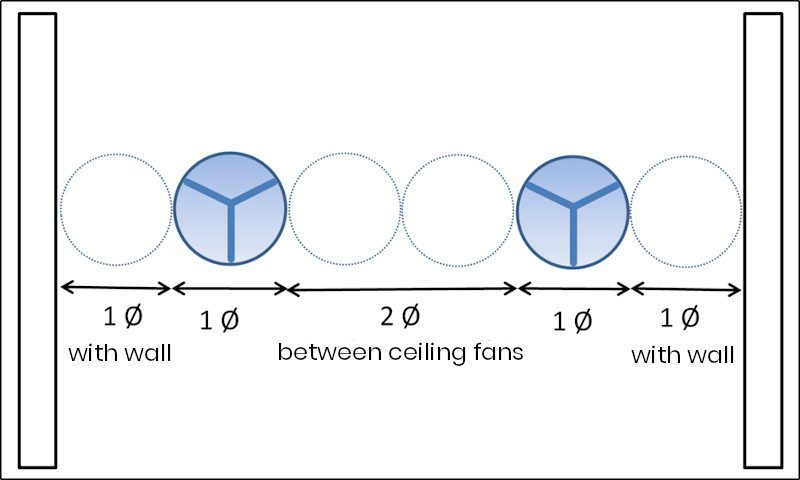
Figure 3 – Recommended minimum spacing between fans and walls
Blade-less ceiling fan layout: more even air distribution
Ceiling fans like those from Exhale Fans have a very specific mode of operation: they send air at high speed (between 3 and 4 m/s) horizontally at ceiling height. The air then bounces off the walls, ventilating the room. Air velocity is more even in the room than with conventional bladed fans, as shown in the illustration below.
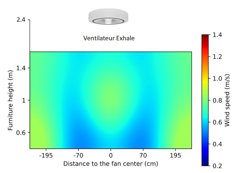
Figure 4 – Air speed distribution with Exhale fan
This visual shows the different air velocities in a room we instrumented in Biot on 28/5/2021.
We used the Testo 400 measuring device, which we positioned at waist, chest and head level in a seated position, at various points in the room.
The full test report is available on request.
Another approach to layout: using an average air velocity calculation?
The new RE2020 environmental regulations have introduced a calculation formula [i] whose usefulness was quickly spotted by professionals.
Here it is:
Air velocity = 0.0032 x circulation rate
- The circulation rate is the ratio of the fan(s) flow rate in m/s to the room volume in m3.
- Air velocity is the average velocity in m/s in the room.
The RE2020 degree-hour calculation is directly impacted by this calculation (see our article on the impact of degree-hours).
In various tests carried out in empty rooms, we have found that this formula approximates reality fairly well.
It is, however, an average speed for a given room as a whole. Thus, at the vertical of a bladed fan, the speed will be higher, but as explained above, as soon as you move more than one diameter away from the outer edge of the blades, the speed drops drastically at the upper part of the body.
From this point of view, a bladeless fan impacts a larger area, albeit with a generally lower airflow than that of bladed fans considered to be high-performance.
It is therefore advisable to keep in mind that the average air speed in a room must be weighted by the type of equipment used, as not all locations in the room will necessarily be well covered.
The visual below, dealing specifically with offices, shows the impact of furniture on air velocity.
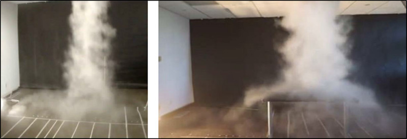
Figure 5 – Impact of a smoke generator simulating a ceiling fan, without and with table; source Gao & Al.
Air velocity and dynamic thermal simulation (DTS)
The desired air speed is also an issue.
For example, air speeds in excess of 1 m/s are not necessarily suitable for office environments (risk of flying leaves).
Although low air speeds can have a beneficial thermal impact, the diagram below [ii] shows that a minimum air speed of 0.30 m/s is required for effective cooling.
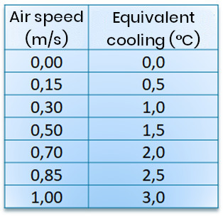
Figure 6 – Diagram from Woods Ventilation Guide..
This is where STD can make a very useful contribution, by simulating the number of hours of discomfort above a given temperature. This can then be used to find an air velocity that will bring about the desired equivalent cooling
Watch out for the stroboscopic effect
This effect is well known to professionals in overseas France, who have been dealing with it for many years.
Lighting and bladed fans don’t always mix. This problem does not exist with bladeless ceiling fans.
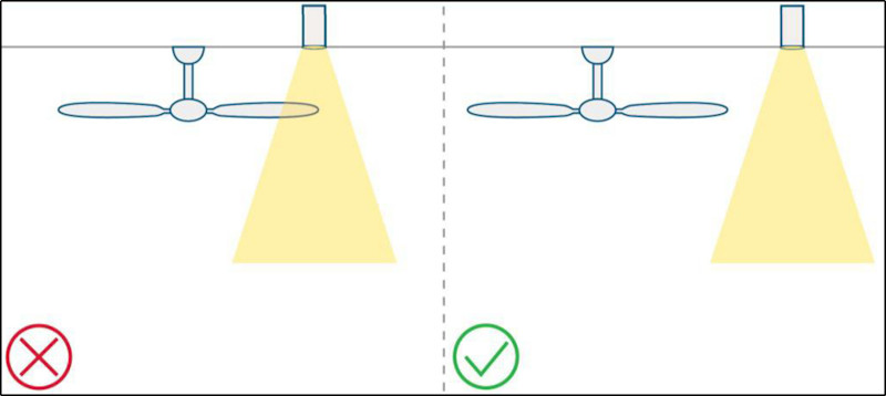
Figure 7 – Blades and light field [iii] To avoid the stroboscopic effect (regular interruption of the light by the passing blades), the blades must be spaced well apart in relation to the light field.

Figure 8 – Blades and light field – layout with slabs [iv] In the case of installation on a false ceiling, care must be taken to position the fans in the adjacent space between 4 luminaires.
Ceiling height: comply with standards
It’s important to comply with safety standard NF EN CEI 60335-2-80. This requires a minimum height of 2.30 m under the blades, and we have published a detailed text on the subject.
Installing ceiling fans: the art and the way
Layout combines two talents.
Firstly, the ability to understand the space, and in particular its interaction with the environment. This means thinking not only about the user, but also about lighting and other networks, which will determine a successful layout.
Secondly, you need to know how to calculate things: whenever possible, use a dynamic thermal simulation, determine the desired air speeds, determine the number of units required in a given room.
So, to ensure the success of your ceiling fan installation projects, always bear in mind this dual approach, and combine technical and aesthetic considerations.
[i] Voir page 979 of the RE2020 calculation method
[ii] The Givoni diagram, which integrates temperature, humidity and air speed, seems well suited to tropical climates, and less operational in the context of metropolitan France. We have little experience of humidity-related discomfort in temperate climates. That’s why we prefer the two-dimensional diagram (temperature and air speed).
[iii] This diagram is taken from the CBE – Berkeley sizing guide.
[iv] Image source: CBE sizing guide – Berkeley.


